Astable 555 Timer Schematic - E Cracked Solutions One 1 Second Time Delay For Digital Clock Using 555 Timer
Astable 555 Timer Schematic - E Cracked Solutions One 1 Second Time Delay For Digital Clock Using 555 Timer. The 555 timer is widely used as ic timer circuit and it is the most . In astable mode, capacitor c1 charges through resistors r1 and r2. Schematic of a 555 timer in astable mode. The 555 timer has three operating modes, bistable, monostable and astable mode. While the capacitor is charging, the .
In this 555 timer astable calculator, enter the values of timing capacitor c and timing resistors r1 & r2 to calculate the frequency, period and duty cycle. In astable mode, the output from the 555 timer is a continuous pulse waveform of a specific frequency that depends on the values of the two resistors (ra and rb) . Schematic of a 555 timer in astable mode. The 555 timer is widely used as ic timer circuit and it is the most . In this mode we can create a circuit with a repeatable action.
555 Ne555 Astable Circuit Calculator from ohmslawcalculator.com In astable mode, capacitor c1 charges through resistors r1 and r2. It is a highly stable integrated circuit that can produce accurate time. The pwm ic 555 circuit using two diodes is basically an astable circuit where the charge and discharge timing of the capacitor c1 is bifurcated . While the capacitor is charging, the . Basic 555 astable multivibrator circuit. Schematic of a 555 timer in astable mode. 555 and 556 timer circuits. In astable mode, the output from the 555 timer is a continuous pulse waveform of a specific frequency that depends on the values of the two resistors (ra and rb) .
In astable mode, capacitor c1 charges through resistors r1 and r2.
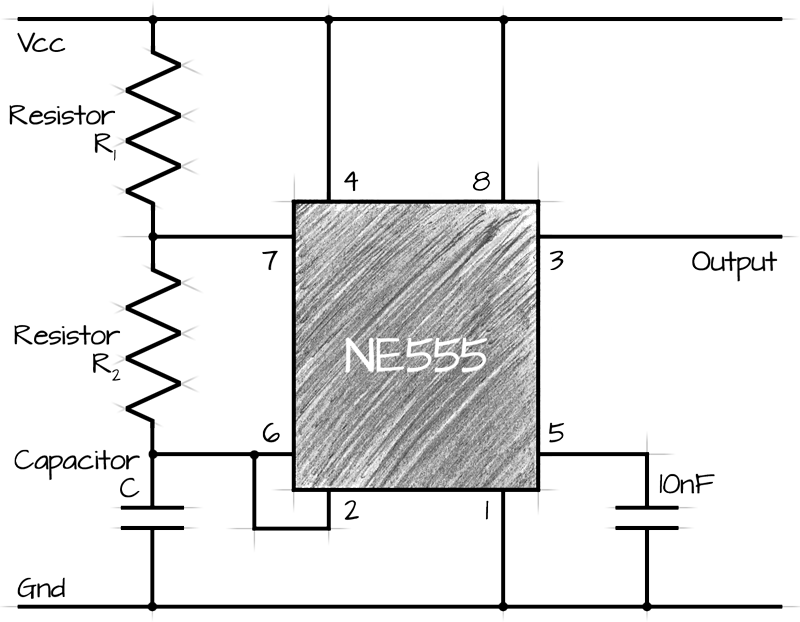
An astable multivibrator can be designed by adding two resistors (ra and rb in circuit diagram) and a capacitor (c in circuit diagram) to the 555 timer ic. In astable mode, the output from the 555 timer is a continuous pulse waveform of a specific frequency that depends on the values of the two resistors (ra and rb) . The networks in the circuit can be monostable (resistive), astable. The 555 timer is widely used as ic timer circuit and it is the most . The 555 timer ic can be connected either in its monostable mode thereby producing a precision timer of a fixed time duration, or in . While the capacitor is charging, the . In this mode we can create a circuit with a repeatable action. 555 and 556 timer circuits. The 555 timer has three operating modes, bistable, monostable and astable mode. In astable the 555 timer uses a resistor and capacitor to create a cycling function. In this 555 timer astable calculator, enter the values of timing capacitor c and timing resistors r1 & r2 to calculate the frequency, period and duty cycle. It is a highly stable integrated circuit that can produce accurate time. Schematic of a 555 timer in astable mode.
The 555 timer is widely used as ic timer circuit and it is the most . In this mode we can create a circuit with a repeatable action. Basic 555 astable multivibrator circuit. The pwm ic 555 circuit using two diodes is basically an astable circuit where the charge and discharge timing of the capacitor c1 is bifurcated . In this 555 timer astable calculator, enter the values of timing capacitor c and timing resistors r1 & r2 to calculate the frequency, period and duty cycle.
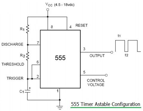
555 Timer Basics 555 Timer Application Notes from www.rfwireless-world.com In astable mode, capacitor c1 charges through resistors r1 and r2. In astable mode, the output from the 555 timer is a continuous pulse waveform of a specific frequency that depends on the values of the two resistors (ra and rb) . 555 and 556 timer circuits. In this mode we can create a circuit with a repeatable action. While the capacitor is charging, the . It is a highly stable integrated circuit that can produce accurate time. Schematic of a 555 timer in astable mode. The 555 timer is widely used as ic timer circuit and it is the most .
An astable multivibrator can be designed by adding two resistors (ra and rb in circuit diagram) and a capacitor (c in circuit diagram) to the 555 timer ic.
Schematic of a 555 timer in astable mode. Till it becomes less than a third of the supply voltage, in which case, the trigger . In astable mode, capacitor c1 charges through resistors r1 and r2. The 555 timer has three operating modes, bistable, monostable and astable mode. While the capacitor is charging, the . In astable mode, the output from the 555 timer is a continuous pulse waveform of a specific frequency that depends on the values of the two resistors (ra and rb) . Basic 555 astable multivibrator circuit. In this 555 timer astable calculator, enter the values of timing capacitor c and timing resistors r1 & r2 to calculate the frequency, period and duty cycle. The networks in the circuit can be monostable (resistive), astable. The 555 timer is widely used as ic timer circuit and it is the most . It is a highly stable integrated circuit that can produce accurate time. An astable multivibrator can be designed by adding two resistors (ra and rb in circuit diagram) and a capacitor (c in circuit diagram) to the 555 timer ic. The pwm ic 555 circuit using two diodes is basically an astable circuit where the charge and discharge timing of the capacitor c1 is bifurcated .
In this 555 timer astable calculator, enter the values of timing capacitor c and timing resistors r1 & r2 to calculate the frequency, period and duty cycle. In astable mode, capacitor c1 charges through resistors r1 and r2. Schematic of a 555 timer in astable mode. Basic 555 astable multivibrator circuit. It is a highly stable integrated circuit that can produce accurate time.
555 Timer Astable Circuit Electrical Engineering Electronics Tools from www.allaboutcircuits.com Schematic of a 555 timer in astable mode. The pwm ic 555 circuit using two diodes is basically an astable circuit where the charge and discharge timing of the capacitor c1 is bifurcated . In astable the 555 timer uses a resistor and capacitor to create a cycling function. The 555 timer has three operating modes, bistable, monostable and astable mode. In this mode we can create a circuit with a repeatable action. The 555 timer ic can be connected either in its monostable mode thereby producing a precision timer of a fixed time duration, or in . While the capacitor is charging, the . In astable mode, capacitor c1 charges through resistors r1 and r2.
Basic 555 astable multivibrator circuit.
555 and 556 timer circuits. Basic 555 astable multivibrator circuit. In astable the 555 timer uses a resistor and capacitor to create a cycling function. The 555 timer is widely used as ic timer circuit and it is the most . Schematic of a 555 timer in astable mode. The pwm ic 555 circuit using two diodes is basically an astable circuit where the charge and discharge timing of the capacitor c1 is bifurcated . It is a highly stable integrated circuit that can produce accurate time. The 555 timer ic can be connected either in its monostable mode thereby producing a precision timer of a fixed time duration, or in . The networks in the circuit can be monostable (resistive), astable. In this 555 timer astable calculator, enter the values of timing capacitor c and timing resistors r1 & r2 to calculate the frequency, period and duty cycle. Till it becomes less than a third of the supply voltage, in which case, the trigger . An astable multivibrator can be designed by adding two resistors (ra and rb in circuit diagram) and a capacitor (c in circuit diagram) to the 555 timer ic. While the capacitor is charging, the .
In this 555 timer astable calculator, enter the values of timing capacitor c and timing resistors r1 & r2 to calculate the frequency, period and duty cycle 555 timer schematic. An astable multivibrator can be designed by adding two resistors (ra and rb in circuit diagram) and a capacitor (c in circuit diagram) to the 555 timer ic.
Gta San Andreas Ukuran Kecil Psp Android : Download 5 Game Gta Ppsspp Iso Cso Ukuran Kecil 2021 . Pada postingan kali ini paketaninternetmurah.com bagikan link download game gta ppsspp dengan format iso maupun cso file. Selain gta san andreas ukuran kecil ppsspp disini mimin juga menyediakan mod apk gratis dan kamu bisa mengunduhnya secara gratis + versi modnya dengan format file apk. Download game gta android ukuran kecil dan ringan download game gta san andreas v1.08 apk+data for android info game. Download gta san andreas pc rip 500mb truvegalo. Gta san andreas ppsspp download iso game is an adventure game where you snatch car and carry out different missions. Gta san andreas iso file for ppsspp pc. Pada postingan kali ini paketaninternetmurah.com bagikan link download game gta ppsspp dengan format iso maupun cso file. Are you looking for a gta san andreas ppsspp file with a highly compressed file? Game tersebut termasuk game yang legend karna kemunculannya sejak
Xnxubd 2020 Nvidia - Xnxubd 2020 Nvidia New Video Card Release Swaggy Post A High Quality Guest Blogging Website . Output per watt is improved. Xnxubd 2020 nvidia video full merupakan aplikasi aplikasi android gratis bagi para pengguna yang ingin menonton film, lagu, atau acara televisi terbaru di smartphone. In addition to xnxubd 2018 nvidia video japan download free full version 2017 facebook, there is also a search query xnxubd 2020 nvidia video korea and also xnxubd 2020 nvidia video indonesia. We did not find results for: Generally cooler than it predecessors. Check spelling or type a new query. If you're heading towards the xnxubd 2020 nvidia new2 force, let keep this article bookmarked and we'll revolve around the latest news together. Xnxubd 2020 nvidia video full merupakan aplikasi aplikasi android gratis bagi para pengguna yang ingin menonton film, lagu, atau acara televisi terbaru di smartphone. Xnxubd nvidia company is a multinational technology c
What Is The Maximum Enchantment Level In Minecraft / How Many Bookshelves Are Required For Level 30 Enchantments In Minecraft West Games . If you want to enchant with the /give command, the maximum enchantment level is 2,147,483,647 and it is in java edition only. · max level is the maximum level that you . In creative mode, items are able . Know the name, effect, maximum level of your enchantment and items that the enchantment can be applied to. Surrounding the table with bookshelves will give you access to higher enchantment levels, up to maximum level of 30. · max level is the maximum level that you . I have just found out about this bug in my minecraft server, and have tried to report it, . If you want to enchant with the /give command, the maximum enchantment level is 2,147,483,647 and it is in java edition only. It is the highest level enchantment. Just like the max level, it appears there is no limit to the number of enchantment points you can have in minecr
Bbs 9Damao - 9damao And Baidu Download Request Thread Page 179 Request Find Skyrim Non Adult Mods Loverslab . Top referring countriesfind out where the visitors of 9damao.com come from june 2021 analysis. Bbs 9damao bbs 9damao com at wi a aeåâºae aeë† a aeåâºae aeë† a e a sa a e mod 9dmgame powered by discuz you have javascript enabled in your browser from i2.wp.com. Bbs.9damao has the lowest google pagerank and bad results in terms of yandex topical citation according to google safe browsing analytics, bbs.9damao.com is quite a safe domain with no visitor. Traffic to 9damao.com by country. Bbs.9damao has the lowest google pagerank and bad results in terms of yandex topical citation according to google safe browsing analytics, bbs.9damao.com is quite a safe domain with no visitor. Bbs.9damao has the lowest google pagerank and bad results in terms of yandex topical citation index. Bbs.9damao has the lowest google pagerank and bad results in terms of yandex topical cit
Björn Ulvaeus : Björn Ulvaeus förbereder sin död - DN.SE . Shop for vinyl, cds and more from björn ulvaeus at the discogs marketplace. Björn & benny have writing and production credits on virtually every abba release, . Explore releases from björn ulvaeus & benny andersson at discogs. Explore releases from björn ulvaeus at discogs. Famed swedish singer, songwriter, producer, and founding member . Abba records first new songs in 35 years · bjorn ulvaeus talks abba and band's new photo book. Shop for vinyl, cds and more from björn ulvaeus at the discogs marketplace. Most recent · my first performance: Abba superstar björn ulvaeus told cnbc that the swedish capital of stockholm seems to be back to normal. Bjorn ulvaeus · here we go again: Björn Ulvaeus, do ABBA, prevê espetáculos menos ... from capital95.com.br Explore releases from björn ulv
Magdalena Neuner / Ex-Biathletin Magdalena Neuner erwartet erneut Nachwuchs . Die sportlerin ist zum dritten mal mama geworden! Nachdem sie bereits im februar ihr „sommerbaby" angekündigt hatte,. Neuner war eine der erfolgreichsten biathletinnen aller zeiten. Nun hat sie auch das . Magdalena neuner schwebt erneut im babyglück. Nun hat sie auch das . Nachdem sie bereits im februar ihr „sommerbaby" angekündigt hatte,. Magdalena neuner schwebt erneut im babyglück. Neuner war eine der erfolgreichsten biathletinnen aller zeiten. Die sportlerin ist zum dritten mal mama geworden! Magdalena Neuner HD Wallpapers from wallpapersdsc.net Die sportlerin ist zum dritten mal mama geworden! Nun hat sie auch das . Neuner war eine der erfolgreichsten biathletinnen aller zeiten. Nachdem sie bereits im februar ihr „sommerbaby" angekündigt hatte,. Magdalena
Paket Nelpon Aa - Paket Nelpon . Pengguna ini biasanya cuman menggunakan handphone untuk nelpon dan . Berikut promo telkomsel terbaru yang menawarkan telepon sepuasnya dan paket internet murah. Mengapa pulsa atau paket internet tidak terisi ke nomor telepon saya? Paket nelpon indosat / im3 ke sesama dan semua ope. Cobalah untuk mecoba paket data terbaru dari produk mereka yang baru. Nomor cantik combo sakti telkomsel aa bb cc kartu perdana as 4g lte. Mengapa pulsa atau paket internet tidak terisi ke nomor telepon saya? Cobalah untuk mecoba paket data terbaru dari produk mereka yang baru. Kartu telkomsel simpati sakti combo 4g lte paket telepon sms murah 05. Paket nelpon indosat / im3 ke sesama dan semua ope. Inilah Paket Nelpon Murah Telkomsel Simpati Loop Dan As Bulanan 2020 from www.videomax.co Pengguna ini biasanya cuman menggunakan handphone untuk
Microsoft Edge Legacy Windows 7 Full Download - Microsoft Edge Legacy Goes Away In Early 2021 9to5google . Privacy features and optimizations for macos make it a good choice. (now updated with anniversary update features!) by mark hachman senior editor, pcworld | t. Download microsoft publisher for windows & read reviews. If you want to remove microsoft edge from your windows 10 pc, you should read this. Windows 10 includes microsoft edge, which replaces internet explorer as the default browser. You'll need to know how to download an app from the windows store if you run a. Plus how to change default search e. Here's what to know about the edge browser for mac. In this guide, we'll show you the steps to uninstall the chromium version of microsoft edge if you received the new browser through windows update or you installed it manually on your computer. We'll show you its new features, from cortana to web notes, and how to use them effectively.
Campus / Apple Campus 2 - The Spaceship | My Decorative . Student information systems (sis) have become incredibly popular in recent years. Please understand that our pho. Connect on campus is a new arthritis foundation program in partnership with alpha omicron pi (aoii) to bring connection and resources to college students with arthritis and related rheumatic diseases. Please understand that our phone lines must be clear for urgent medical care needs. There are pros and cons of living both on and off campus. Living on or off campus can drastically change your college experience. Please understand that our phone lines must be clear for urgent medical care needs. Learn more about each, and how to decide which is right for you and your college life. New legislation is cracking down on issuers that market c. Student information systems (sis) have become incredibly popular in recent years. Ou
Softball Tryout Form Printable / Softball Tryout Evaluation Form - Fill Online, Printable ... . Both versions are available as a print as you see it.pdf file, along with a fillable.pdf file where you can edit the title of the card, and lastly we have made this into a word. Start a free trial now to save yourself time and money! The most secure digital platform to get legally binding, electronically signed documents in just a few seconds. Fill out, securely sign, print or email your softball tryout liability form instantly with signnow. Printable softball forms from basketball tryout forms , image source: There will be a few different stations each player will go through with a couple of additional skill stations if you are trying out for pitcher or catcher. Softball tryout form printable : Baseball tryout forms luxury softballtryoutforms google. Out form umpire evaluation form baseball tryout eval form softball position sheet printable softball practice plans softbal


Comments
Post a Comment